Bell X-1 Revell 1/32 # 85-5862 Review

RoR Step-by-Step Review 20111120* – Bell X-1 Revell 1/32 #85-5862 Review
Click Here to Buy This Kit
Â
Â
Review and Photos by Todd McWilliams  Â
Â
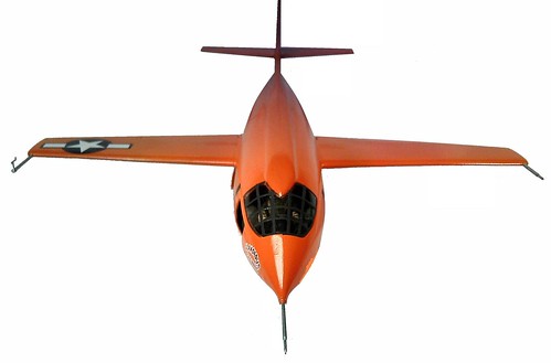
Timeline October 14, 1947: The Bell X-1 became the first airplane to fly faster than the speed of sound. Less than 30 days earlier, the former United States Army Air Corps (USAAC) became the newly formed United States Air Force (USAF). On this day, the X-1 was air-launched at an altitude of 7,000 meters (23,000 feet) from the bomb bay of a specially modified Boeing B-29. Piloted by U.S. Air Force Capt. Charles E. “Chuckâ€, the X-1 reached a speed of 1,127 Kilometers (700 Miles) per hour, Mach 1.06, at an altitude of 13,000 meters (43,000 feet). The X-1 was fueled by a volatile mixture of alcohol and liquid oxygen.
Â
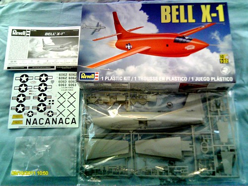
Fig 001) – This Revell kit #85-5862 is a skill level 2 with a 50 parts count in clear and gray colored plastic. The length of the finished model is 12-3/4†and a wing span of 10-5/8â€. The kit features a fully detailed cockpit with an optional pilot figure, an optional rocket engine, an opening cockpit door and a large decal sheet with authentic markings for four versions.
Â

Fig 001a) – I believe this is the third release of the Bell X-1 1/32 scale kit. For you kit collectors, the first release is kit number #4565 with orange colored plastic and the second release is kit #85-4565 with gray colored plastic. Yeager named the airplane “Glamorous Glennis†in tribute to his wife.
Â
First off, I had to really do my homework and search the internet for reference material to get started on this kit. Already having a strong interest in X planes already, this is one X plane I wanted to get as close to correct as possible. I had been gathering reference material and photos for a few years but the actual snag was trying to locate cockpit interior photos, whether they be B&WÂ or color photos. I had plenty of exterior reference photos but no interior ones. About 3 weeks ago, I hit the jackpot! I searched a little longer and a little harder and found five color and one B&W photos. Pay dirt!
Â
The next research items were the colors for both the exterior and the interior. The government uses a FS or Federal Standard system to reference colors of paints. If you have ever referenced a Federal Standard paint list you will notice that it not only shows colors but also the hues or tones of colors, so be prepared to look at a lot of different colors!
Â
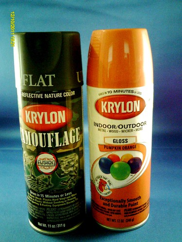
Fig 002) – After searching numerous model chat groups and model sites for paint information on the Bell X-1, the closest that would come to the actual basic color of the interior is Krylon Ultra-Flat Camouflage Olive color #4253 in the 11oz rattle can. The color looks to be a darker shade of olive drab with a splash of gray in it. Between searching online and about 4 local businesses, I was finally able to locate a can. The exterior color is a FS 12246 orange and another story. I was told that the closest color to the actual orange is a Floquil color caller “Reefer Orangeâ€, actually a railroad color in a small bottle which has to be airbrushed. While looking at a local K-Mart, they were closing out Krylon paints to be replaced with Duplicolor brand paint. One of the cans of paint was an orange color that looked perfect for the FS 12246 orange, labeled “Pumpkin Orangeâ€.
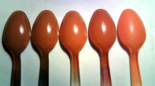
Fig (002a) – Let me cut in and say a few words about the “Spoon Test†with paints. When I’m testing what primers to use under what colors of paints, I use plastic spoons like you’d use at a picnic. They are made out of styrene plastic so they would accurately represent the plastic parts you would be ultimately spraying. Starting from right to left, I sprayed in that order, white primer, red oxide primer, gray primer, dark hot rod primer and finally on the left, black primer. I then sprayed the “Pumpkin Orange†on each of the primed spoons. On the far right, the white primed spoon with the orange color came the closest to the actual FS 12246 orange. This was shown to be the closest by bringing up the FS 12246 orange color on the computer screen. While not a truly 100% accurate way to measure the matchup, it sure was close enough for me. I will add at this point that any flashing was very minimal, so cleanup of parts was made easier.
Â
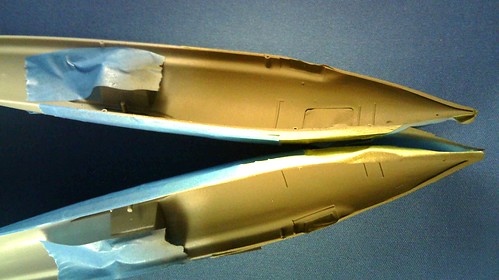
Fig 005) – Paint and build: I started by masking off the edges of the fuselage and sprayed the Krylon Camouflage green mentioned. The seat and interior parts were sprayed also.
Â
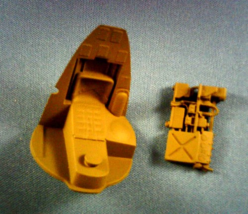
Fig 006) – While these were drying, I started on the pilot figure. I cut to the chase by gluing the pilot halves together. The figure was temporarily taped to the seat to position where the arms/hands would finally be and glued in place. The head will be attached later after painting. Once the glue dried, the figure was primed in gray, seams filled and sanded and painted. The head was primed, seams filled, sanded and primed again to be painted alongside the body.
Â

Fig 007) – Prior to finish painting the body and head, I researched the colors of the uniform, jacket, and all of the accessories associated with the figure. I found numerous sites that had photos of the actual WW II items such as the helmet and air canister/mask. As in building and model or replica, you can’t do too much research through photos!
Â
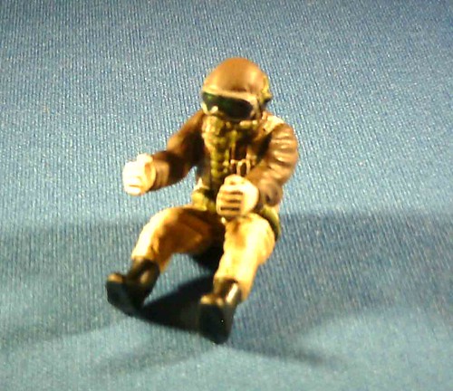
Fig 012) – The figure was finish painted in acrylic hobby paints. When it was dried, a coating of acrylic artists spray was applied to seal in the hand painted acrylic colors. After that, I brush applied oil based dark brown stain to add the shaded areas and give the figure a weathered look (insert photos #007 & #012).
 Â

Fig 015) – The kit supplied clear peg (see # 12 in the instruction sheet), that is supposed to keep the nose down on the ground would have interfered with the realistic look I was trying to achieve. I wanted to add sufficient weight to the front/nose of the model to eliminate the clear peg and let the aircraft stand on its own. To do this, I built a small box for the back of the pilot seat to house a number of BB’s plus a few BB’s in the very front nose that I glued in with 5 minute epoxy. In the end, this was just enough weight to keep the nose from going sky high prematurely! Photo 015 shows the assembly with the pilot seat, the BB box in back and the BB’s up in the nose part for reference.
Â
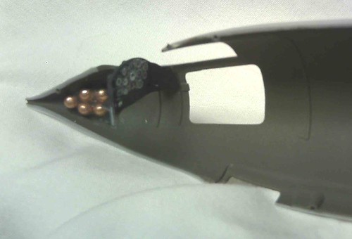
Fig 016) – Photo 016 shows the opposite side of the fuselage with the instrument panel glued in place. Prior to attachment; the instrument panel was spray painted with black primer. Once dried, a coat of the acrylic artists spray was applied to give it a matte finish. The kit supplied decals were applied with Solvaset brand decal setting solution applied to settle the decal in the recesses. I have found that you need to test any setting solution prior to use as you may damage the decal as some solutions may be too “hotâ€. In this application, Solvaset was just right for the panel decal to lie down.
Â
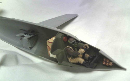
Fig 019) – I temporarily taped the two halves of the fuselage together to position the instrument panel in place. Once the panel was where it should be, I glued one side of the instrument panel to one side only by applying the glue with a toothpick through the canopy opening. The same operation was done with the foot rudder pedals. This way when you separate the two halves (after the glue has dried overnight), the panel and the pedals will stay in alignment when it comes time to finally glue the two halves together. You will notice that I glued the wing halves together and glued these and the rear right and left stabilizers in their prospective locations in the fuselage prior to the fuselage halves being glued together. I do this for ease of assembly later. You, the reader, will find that I use the kit supplied instructions merely as a reference guide, but you may wish to build the aircraft by following the instruction sheet to a “Tâ€, your choice. Having been a Tool Maker/Machinist for 37 years, my mind tends to unravel and figure out alternate means of assembly to accommodate the construction sequence.
 Â
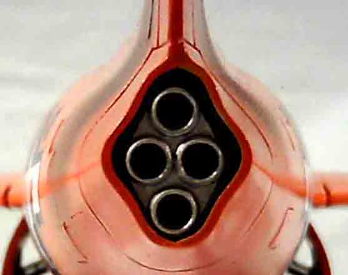
Fig 020) – Next, the kit supplied engine was assembled. The engine has two positioning pins that mate it to the one fuselage half. This particular model kit had the forward pin about ¼†longer than it should have been, I attribute this error to a broken ejector pin in the mold. The pin was cut and trimmed to the proper length. It was then sprayed with a gray primer, then silver automotive touchup paint was applied and a finish coat of dullcoat to tone it down and give it a more gun metal color and look. The finished engine was glued in place as per the instruction sheet. You may ask yourself, “Why is he installing the finished engine in the fuselage when he hasn’t even color painted the aircraft itself?†This will be covered next when I explain how I masked the aircraft off for spraying.
Once I was pleased that all the necessary interior work had been done, I proceeded to the job of masking everything off, or masking in, in this case! I’ll jump to the engine masking first. I knew that I had ample space between the engine and the rear fuselage halves, so I used blue, low tack painters tape to wrap the exposed rear part of the engine and pinched the tape closed. I switched to the light green auto body masking tape to tape off, from the inside of the side entrance opening and the canopy opening. I had to do both of the fuselage halves separately in the canopy area, bringing the tape edge in line with the parting line where the two halves come together, this way the two fuselage halves could be glued together afterwards without interference from the tape. All this planning pays off as everything comes together. It is a lot to think about, almost like looking at the end project and planning backwards.
The next step was to glue the two fuselage halves together using Testor’s thick liquid glue. This way it wouldn’t dry too quickly while I’m putting the two halves together, with everything in alignment. Once everything looked like a “GOâ€, all my clamps, clothes pins, tape and rubber bands did their thing to hold everything together. Again, and I can’t stress enough, the careful planning pays off!
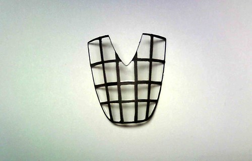
Fig 022) – With the fuselage assembly set aside, I set about prepping the canopy for painting. I have a really good steady hand for hand painting, but I decided to mask off the canopy to paint the black lines on the outside of the canopy. This was accomplished with Bare Metal Foil (BMF). After applying a single piece over the whole outside of the canopy, I carefully trimmed out each glass panel and removed the lines that will leave the area to be painted. Remember, we’re working in reverse here, so make sure you remove the correct pieces of BMF leaving the “glass†panels covered. I then taped the inside of the glass to prevent any overspray from getting on the inside of the glass. You have to think of everything in advance. Once the canopy was ready, I sprayed the exposed lines with black automotive primer in the rattle can to give it a flat look. This was set aside to dry. The photo shows the finish painted canopy after all the masking was removed.
Â
Now, let’s get back to the assembled fuselage. Even though the masking along the canopy parting lines may not meet, I used small strips of tape to seal off any open areas where overspray can get in. After doing this, I still found a couple of small pinhole areas that paint could have gotten in. This is where rubber cement comes in. With a pointed toothpick, rubber cement was applied and sealed the canopy and the side door area in. At this point I assembled the Strut Support and the Oleo Support together without gluing them to the aircraft themselves. That way they could be removed as a unit, painted separately and reinstalled later with the wheel attached. Assembled units are always easier to work with. The painting as accomplished in between those two steps.
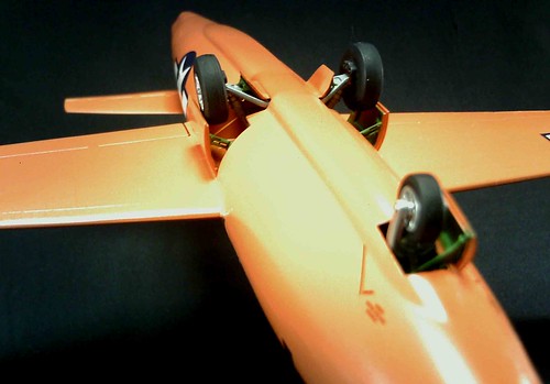
Fig 025) – You will notice that the strut support has two small mounting pins that attach to two small holes in the landing gear area on the bottom of the plane. (See #6 in the kit instruction sheet) I measured these holes and they happen to be 1/16†in diameter. I had some 1/16†diameter aluminum round welding rod about 6†long, so I fed the rod through the holes, twisted the ends as to make a handle to hold the model while spraying it with paint. Instant handle! Now we’re ready for putty, sanding and paint! I sanded the seams, puttied what was needed and cleaned up what needed to be cleaned up.
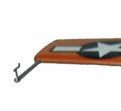

Fig 23 – 24) At this time, I attached the Nose Pivot, the Wing Pitot and the Slip Indicator. With all the research I did, plus going to the Air and Space Museum in Washington DC to see the actual Bell X-1, the Wing Pitot and the Slip Indicator had to be switched from what the instruction sheet would have you do. Also the downward spear on the Wing Pitot needed to be cut off leaving just a pointed spear. The Slip Indicator had to be turned so that the antenna piece is on top.
With all the prep work done, I sprayed the model with white automotive primer. Once the primer was dried, I did any necessary additional sanding to get ready for the color coat. I ended up emptying out a can of the Krylon “Pumpkin Orange†into a container, inside of a white trash bag by using a small can opener to punch a hole in the bottom of the can while in an upright position. This releases the air pressure and allows you to drain the can of paint when the air has diminished. A little bit of a mess (thus the trash bag to catch any mess) but you can drain the can to airbrush the contents later. Once the paint was in the container, I let the paint settle to the bottom and then removed most of the solvent without disturbing the settled paint. I then added about 3 tablespoons of lacquer thinner to speed up the drying time of the orange color coat. I then airbrushed the model along with the side entrance door, gear doors, main doors and the nose door, everything that had to be orange. Once the paint dried on all of the parts, I sprayed automotive clear to give it a little bit of a shine. I then hand painted the green zinc oxide on the inside of the doors and needed areas. The three assembled tires were sprayed with black primer and the wheels hand painted with silver paint. These were sprayed with artist’s acrylic matte to give the tires a slight sheen and tone the silver paint down at the same time.

Fig 028) – Final assembly: With everything dried, cured and ready to go, I attached all of the doors to their perspective locations and the wheels/tire assembly to the struts. Once assembled, the decals were the last item on the agenda. Here we have the finished model!
Final impressions: This has been a model I have wanted to build ever since Revell first released the kit years ago. Revell did a beautiful job of covering the second most important aircraft in history, the first being the Wright Flyer and Revell has that one covered too! Would I build this kit again? Sure would, in a heartbeat!
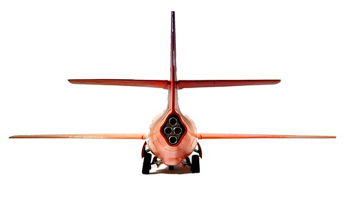
Fig 999
Â
Remember: This is a hobby. Keep it fun and enjoyable!
Todd McWilliams
Â
*All Registered trademarks are the property of their respective brands.
Â
Â